Aug 13, 2026
How Cast & Helix Defects Ruin Robotic Welding with High-Strength Solid Wire
ER80S-D2 / ER100S-G robotic welding plagued by bird-nesting, spatter, and downtime? Learn how poor cast and helix tolerance cause feeding failures
How Cast & Helix Defects Ruin Robotic Welding with High-Strength Solid Wire
The Hidden Problem: Feeder Troubles Are Often Wire Quality Issues
Your robotic welding cell keeps stopping. The wire snags inside the liner. You get bird-nesting at the drive rolls. The arc is unstable. Spatter is everywhere. And intermittent porosity ruins weld quality.
You check the feeder. You check the gun. You check the liner. Everything looks fine. But the problem persists.
Here is what many fabricators miss: the root cause may not be your equipment — it is your wire.
This is especially true for alloy-rich high-strength grades like ER80S-D2, ER90S-D2, ER100S-G, and ER110S-G. These wires are harder and less ductile than mild steel wires. They demand tighter manufacturing tolerances. When those tolerances slip, your robotic welding operation pays the price.
Why It Happens — The Mechanics of Poor Cast & Helix
To understand the problem, you need to know two terms: cast and helix.
Cast refers to the diameter of the circle the wire naturally forms when laid on a flat surface. If the cast is too large or too small, the wire does not feed straight through the liner. It presses against the liner wall, creating friction.
Helix refers to the vertical deviation — how much the wire spirals up off the flat surface. Excessive helix means the wire twists as it feeds, causing erratic movement through the contact tip.
For robotic MIG welding, these tolerances are critical. Robots run continuously at high feed speeds. Any variation in wire straightness gets amplified. The wire snakes inside the liner, causing:
- Bird-nesting — wire tangles at the drive rolls
- Unstable arc — inconsistent wire feed affects arc length and stability
- Excessive spatter — erratic feeding disrupts the droplet transfer
- Random porosity — inconsistent arc affects gas shielding effectiveness
- Contact tip wear — off-center wire wears the tip unevenly
Real-World Cost: Downtime, Scrap, and Rework
The impact on your bottom line is significant. Each stoppage costs:
Cost Factor | Impact |
|---|---|
Lost production time | 10-30 minutes per unplanned stop, multiple times per shift |
Scrap parts | Failed welds mean rejected components |
Rework labor | Grinding out and rewelding defective joints |
Consumable waste | Contact tips, liners, and drive rolls wear faster |
Robot programming | Frequent stops disrupt automated cycles |
For high-volume robotic welding operations, even one feeding failure per hour can reduce overall equipment effectiveness (OEE) by 15-20%. That is a productivity loss your competition cannot afford.
3 Steps to Solve Robotic Feeding Failures
1. Source Stress-Relieved Solid Wires
Not all high-strength solid wires are manufactured with robotic welding in mind. The best products undergo a stress-relieving process during manufacturing. This reduces residual curvature and ensures the wire holds its intended cast and helix tolerances.
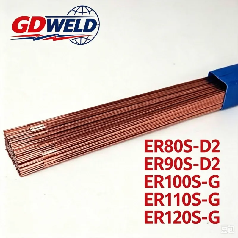
GD-WELD high-strength solid wires — ER80S-D2, ER90S-D2, ER100S-G, and ER110S-G — are produced with precise annealing and controlled spooling to deliver consistent, predictable feeding performance.
2. Control Helix Tolerance for Robot MIG Welding
AWS specifications allow a certain range of cast and helix. But for robotic welding, tighter is better. Reputable wire suppliers control helix to within 1.6 mm (1/16 inch) over a 300 mm (12 inch) length.
When selecting a wire for automated applications:
- Require documented cast and helix test reports
- Choose suppliers who test every batch
- Avoid budget wires that only meet minimum AWS tolerances
3. Maintain Welding Accessories Regularly
Even the best wire will not feed properly through worn equipment. Implement a routine maintenance schedule:
- Replace liners every 100-200 kg of wire, or sooner for alloy-rich grades
- Inspect drive rolls for wear and proper tension
- Clean or replace contact tips regularly
- Check inlet and outlet guides for burrs or misalignment
Batch-to-Batch Consistency Is Non-Negotiable
Robotic welding demands repeatability. Your wire must perform the same way spool after spool, batch after batch.
The difference between a reliable wire and a problem wire often comes down to manufacturing control:
Quality Factor | What It Means |
|---|---|
Precise annealing | Removes residual stress for consistent cast |
Controlled drawing process | Maintains diameter tolerance within ±0.02 mm |
Clean spooling | Prevents layer cross-over and tangling |
In-process testing | Verifies cast and helix on every coil |
Without these controls, you are introducing a variable into your automated process that no robot programmer can fix.
Get Stable Robotic Welding Performance
Your robotic welding cell is a significant investment. Do not let poor wire quality undermine your return on that investment.
GD-WELD high-strength solid wires are engineered for automated welding applications:
- Stress-relieved for stable cast and helix
- Tight diameter tolerance for smooth feeding
- Clean, consistent spooling to prevent tangling
- Available in ER80S-D2, ER90S-D2, ER100S-G, and ER110S-G
Switch to a wire that works with your equipment — not against it.
FAQs
Q: What is the difference between cast and helix?
A: Cast is the natural curvature of the wire when laid flat; helix is the vertical spiral off the flat surface. Both affect how the wire travels through the liner.
Q: Why are high-strength solid wires more prone to feeding problems?
A: Alloy-rich grades like ER80S-D2 and ER100S-G are harder and less ductile than mild steel wires. They retain more residual stress from the drawing process, making cast and helix control more critical.
Q: Can I solve feeding problems by adjusting drive roll tension?
A: Partially, but this is a band-aid. Too much tension deforms the wire; too little allows slipping. If the wire has poor cast or helix, tension adjustments alone cannot fix the root cause.
Q: What helix tolerance should I specify for robotic welding?
A: For robotic MIG welding, look for helix within 1.6 mm (1/16 inch) over a 300 mm (12 inch) length. Tighter tolerances mean smoother feeding.
Q: How often should I replace welding liners for high-strength wire?
A: For alloy-rich wires, replace liners every 100-200 kg of wire consumption, or sooner if you notice feeding resistance.